CNC 4-roller hydraulic plate roller
A 4-roller plate roller pre-bends the plate end and rolls in one pass — the plate is fed once, and pre-bending and roll forming complete without turning the head. That is the whole point of the four-roll layout, and it is why these machines are the default for tanks, towers and pressure work.
Machine features
- Strong generality — the 4-roller plate rolling machine has the pre-bending function of the plate end and the CNC rolling function
- Feed the metal plate at a time; pre-bending and roll forming complete without turning the head
- The upper working roll is the main drive roll; the lower roll and both sides of the roll are hydraulically driven
- Lift displacement controlled by the computer and automatically levelled; screen display synchronisation accuracy ±0.1 mm
- Tilting and resetting of the rollover bearing body by hydraulic transmission; upper roll balance mechanism for easy workpiece removal
- Mobile stand-alone console that can be moved at any time; safety interlocking device fitted
- Full-featured, high-precision, easy to operate — the ideal contemporary CNC coiling device
Standard and optional equipment
| Standard equipment | Optional equipment |
|---|---|
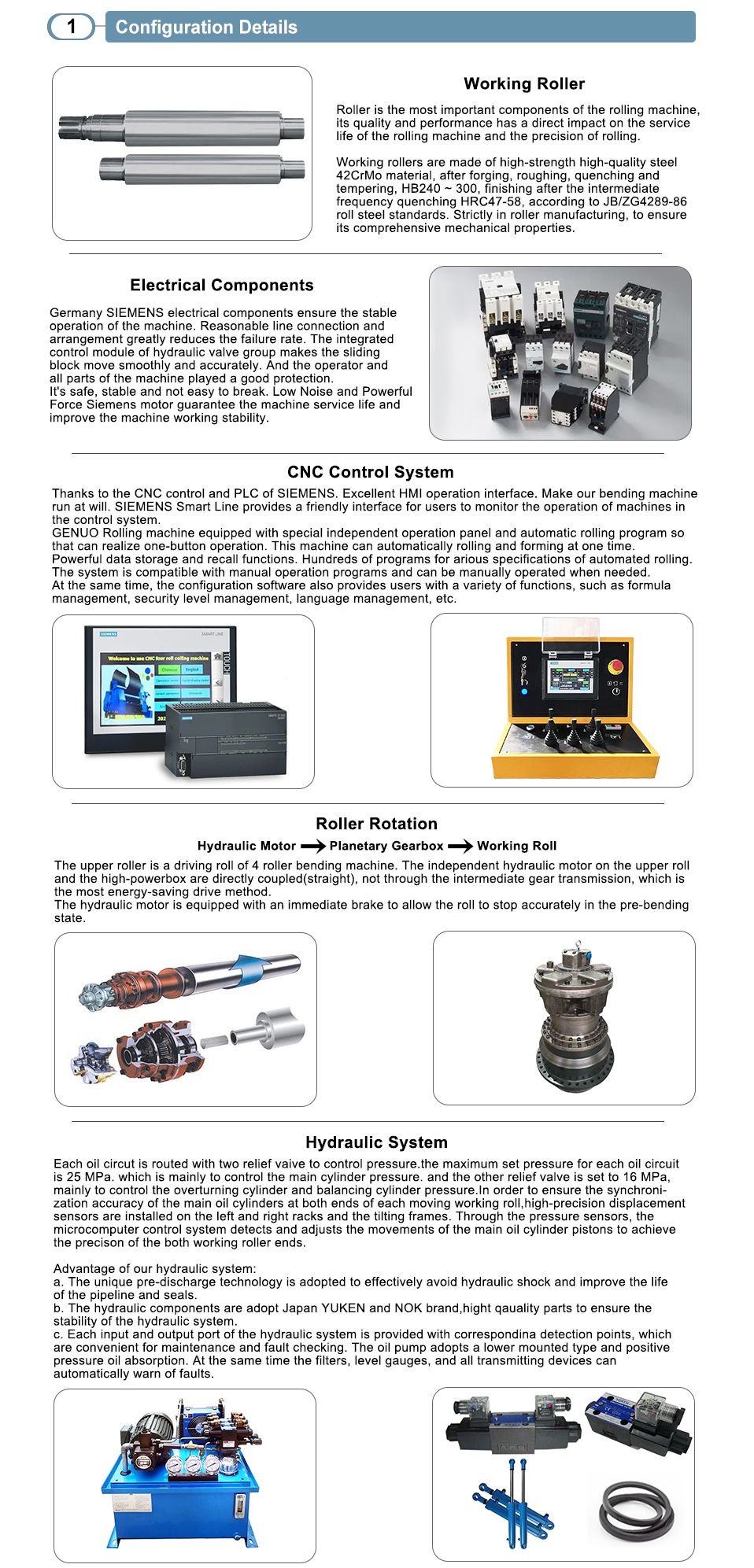
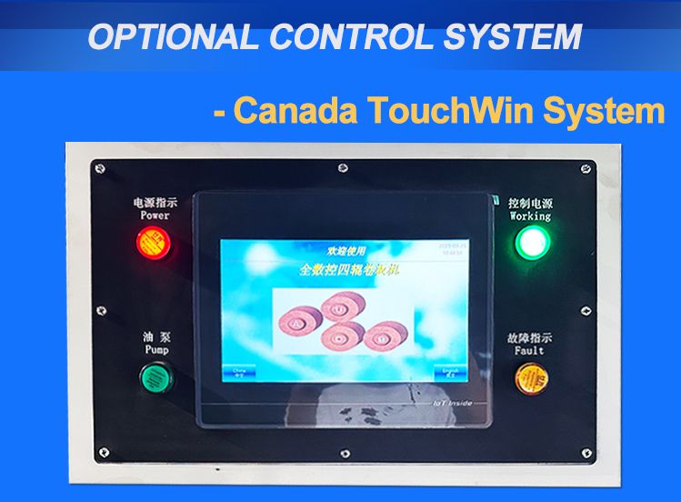
| Siemens PLC controller, touch display | Siemens CNC control system |
| 42CrMo solid forging roller | Central and side supports |
| Schneider & Omron electrical components | Automatic loading and unloading systems |
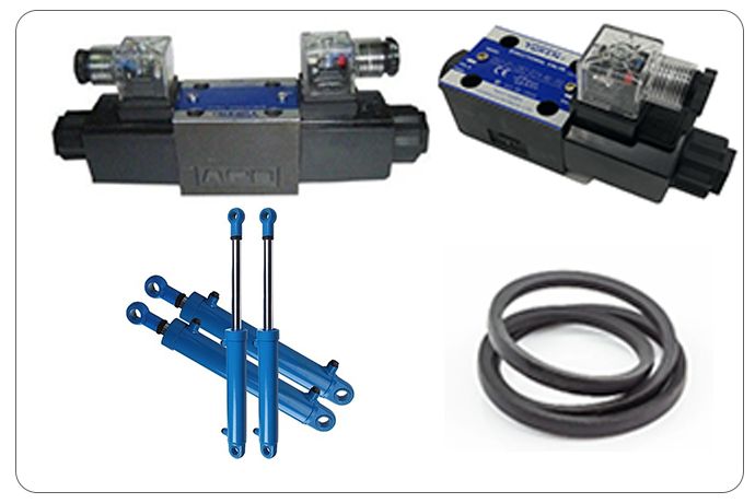
| YUKEN hydraulic valves, NOK seal ring | Motorised feeding and squaring tables |
| NSK double-row spherical roller bearing | Side motorised rolls |
| Tamagawa precision rotary encoder | Provision for hot rolling |
| Siemens main motor, Sunny pump | Integrated welding system |
| iNi hydraulic motor, Peika planetary reducer | Automatic lubrication system |
| Mobile wheel-mounted control console | Automatic ejector |
| Centralised manual lubrication | Customised colours |
Technical specification — HC4R range
| Model | Max pre-bend (mm) | Max rolling (mm) | Max width (mm) | Yield (MPa) | Speed (m/min) | Upper roller ø (mm) | Lower roller ø (mm) | Side roller ø (mm) | Motor (kW) |
|---|---|---|---|---|---|---|---|---|---|
| 6×2000 | 6 | 6 | 2000 | 265 | 5.5 | 180 | 180 | 145 | 5.5 |
| 6×2500 | 6 | 6 | 2500 | 265 | 5 | 210 | 210 | 165 | 7.5 |
| 8×2000 | 6 | 8 | 2000 | 265 | 5 | 215 | 215 | 165 | 11 |
| 8×2500 | 6 | 8 | 2500 | 265 | 5 | 230 | 230 | 180 | 11 |
| 12×2000 | 10 | 12 | 2000 | 265 | 5 | 260 | 260 | 200 | 18.5 |
| 12×2500 | 10 | 12 | 2500 | 265 | 5 | 280 | 280 | 220 | 18.5 |
| 16×2000 | 12 | 16 | 2000 | 265 | 5 | 280 | 280 | 220 | 18.5 |
| 16×2500 | 12 | 16 | 2500 | 265 | 5 | 330 | 330 | 260 | 22 |
| 16×3200 | 12 | 16 | 3200 | 265 | 5 | 360 | 360 | 280 | 30 |
| 20×2000 | 16 | 20 | 2000 | 265 | 5 | 330 | 330 | 260 | 22 |
| 20×2500 | 16 | 20 | 2500 | 265 | 5 | 360 | 360 | 280 | 30 |
| 25×2000 | 20 | 25 | 2000 | 265 | 5 | 360 | 360 | 280 | 30 |
| 25×2500 | 20 | 25 | 2500 | 265 | 4.5 | 410 | 400 | 320 | 37 |
| 30×2000 | 25 | 30 | 2000 | 265 | 4.5 | 410 | 400 | 320 | 37 |
| 30×2500 | 25 | 30 | 2500 | 265 | 4.5 | 470 | 470 | 390 | 37 |
| 30×3000 | 25 | 30 | 3000 | 265 | 4.5 | 560 | 520 | 420 | 45 |
| 40×2500 | 35 | 40 | 2500 | 265 | 4.5 | 560 | 520 | 420 | 45 |
| 40×3000 | 35 | 40 | 3000 | 265 | 4.5 | 650 | 580 | 480 | 55 |
| 50×2500 | 40 | 50 | 2500 | 265 | 4 | 650 | 620 | 500 | 55 |
| 50×3000 | 40 | 50 | 3000 | 265 | 3.5 | 720 | 650 | 520 | 55 |
| 60×3000 | 50 | 60 | 3000 | 265 | 3 | 750 | 710 | 560 | 75 |
| 70×3000 | 60 | 70 | 3000 | 265 | 3 | 750 | 720 | 600 | 75 |
| 80×3000 | 70 | 80 | 3000 | 265 | 3 | 800 | 780 | 620 | 75 |
| 90×3000 | 80 | 90 | 3000 | 265 | 3 | 840 | 820 | 660 | 90 |
All models at 265 MPa plate yield limit. Machine structure drawing with numbered components (overturn cylinder, frames, rollers, balancing system, hydraulic and electronic control systems) is supplied on request.
Roller rotation
Hydraulic motor → planetary gearbox → working roll. The upper roller is the driving roll of the 4-roller bending machine. The independent hydraulic motor on the upper roll and the high-power gearbox are directly coupled (straight), not through intermediate gear transmission — the most energy-saving drive method. The hydraulic motor is equipped with an immediate brake, allowing the roll to stop accurately in the pre-bending state.
Electrical and hydraulic systems
- Germany Siemens electrical components — reasonable line connection and arrangement greatly reduces the failure rate; the integrated control module of the hydraulic valve group makes the sliding block move smoothly and accurately, protecting the operator and all parts of the machine
- Each oil circuit is routed with two relief valves to control pressure; the maximum pressure set for each oil circuit ensures synchronisation accuracy of the main oil cylinder at both ends of each moving working roll
- High-precision displacement synchronisation: sensors installed on the left and right racks and tilting frames, microcomputer control system detects and adjusts the movements of the main oil cylinder pistons
- Oil pumps adopt Japan YUKEN and NOK brand, high-quality parts to ensure the stability of the hydraulic system; input and output port of the hydraulic system provided with corresponding detection points, filter level gauges and transmitting devices that can automatically warn of faults
- Siemens motor guarantees machine service life and improves working stability
Ask about the cnc 4-roller hydraulic plate roller
Send the part you need to bend and we will come back with a configuration and a quote.